You have no items in your shopping cart.


Which OBD-II Protocol is Supported By My Vehicle?
This entry was posted on January 26, 2004.
All cars and light trucks built for sale in the United States after 1996 are required to be OBD-II compliant. The European Union OBD legislation is somewhat more complicated.
An OBD-II compliant vehicle can use any of the five communication protocols: J1850 PWM, J1850 VPW, ISO9141-2, ISO14230-4 (also known as Keyword Protocol 2000), and more recently, ISO15765-4/SAE J2480 (a "flavor" of CAN). US car manufacturers were not allowed to use CAN until model year 2003, but as of model year 2008 and going forward, all vehicles will use the CAN protocol.
There are two types of diagnostic link connectors (DLCs) defined by SAE J1962 - Type A and Type B, shown in Figures 2 and 3, respectively. The main difference between the two connectors is in the shape of the alignment tab.
Location - According to J1962, Type A DLC "shall be located in the passenger or driver's compartment in the area bounded by the driver's end of the instrument panel to 300 mm (~1 ft) beyond the vehicle centerline, attached to the instrument panel and easy to access from the driver's seat. The preferred location is between the steering column and the vehicle centerline."
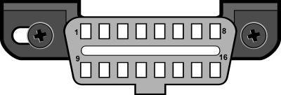
Fig. 1 - J1962 Vehicle Connector, Type A
Type B DLC "shall be located in the passenger or driver's compartment in the area bounded by the driver's end of the instrument panel, including the outer side, and an imagined line 750 mm (~2.5 ft) beyond the vehicle centerline. It shall be attached to the instrument panel and easy to access from the driver's seat or from the Co-drivers seat or from the outside. The vehicle connector shall be mounted to facilitate mating and unmating."
</
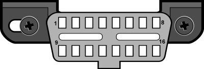
Fig. 2 - J1962 Vehicle Connector, Type B
As a general rule, you can determine which protocol your vehicle is using by looking at the pinout of the DLC:
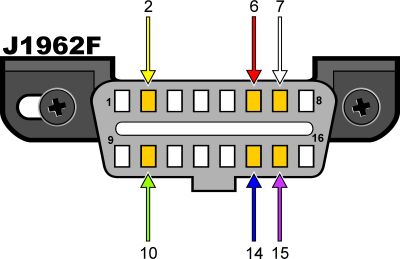
Fig. 3
The following table explains how to determine the protocol:
| Pin 2 | Pin 6 | Pin 7 | Pin 10 | Pin 14 | Pin 15 | Standard |
|---|---|---|---|---|---|---|
| must have | - | - | must have | - | - | J1850 PWM |
| must have | - | - | - | - | - | J1850 VPW |
| - | - | must have | - | - | may have* | ISO9141/14230 |
| - | must have | - | - | must have | - | ISO15765 (CAN) |
*Pin 15 (also called the "L-line") is optional in newer vehicles that use the ISO9141-2 or ISO14230-4 protocols.
In addition to pins 2, 7, 10, and 15, the connector should have pins 4 (Chassis Ground), 5 (Signal Ground), and 16 (Battery Positive). This means that:
PWM The connector must have pins 2, 4, 5, 10, and 16 VPW The connector must have pins 2, 4, 5, and 16, but not 10. ISO The connector must have pins 4, 5, 7, and 16. Pin 15 may or may not be present. CAN The connector must have pins 4, 5, 6, 14, and 16
And lastly, you may find this page helpful:
OBDII Generic Communication Protocols by Manufacturer
